 English
 中文
中文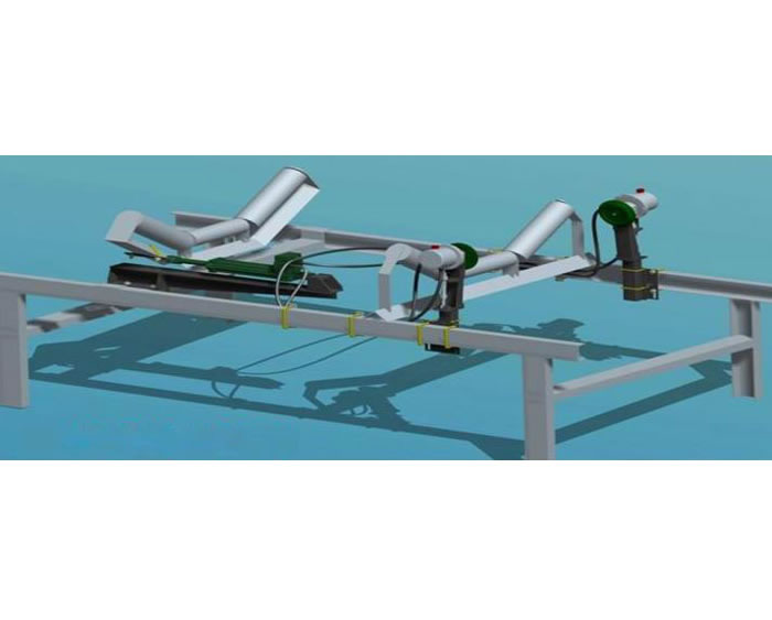
- Product name:Passive automatic correction
- Product number:
- Usage accuracy:
- Product Overview:


1.Overview
On the basis of absorbing domestic and foreign technology and years of experience in manufacturing belt conveyor protection devices, Xuzhou Yike Electric Co., Ltd. has independently developed a new type of high-efficiency passive hydraulic deviation correction device, which is widely used in belt conveyor systems in industries such as metallurgy, mining, power, building materials, coal, etc. It is an ideal equipment for preventing and correcting belt deviation
2. Characteristics
The hydraulic deviation correction device acts on the upper and lower center rollers. When the belt deviates, it actively adjusts the angle of the correction drag roller to correct the belt. This not only eliminates the need for vertical rollers to protect the edge of the belt from friction damage, but also quickly corrects the belt. Automatically detect and correct belt deviation, ensuring that the belt is always in a reasonable state of operation. It has a good adjustment effect on belt deviation caused by improper installation, operation failure, material impact, load changes, and uneven elongation between belt sections
The power of the device is the hydraulic power generated by the friction and rotation of the belt and the detection wheel, so it does not need power supply, and has the characteristics of automatic adjustment, Autocorrection, simple structure, reliable performance, convenient installation, The device adopts a fully enclosed structure, so it can work normally in any harsh environment
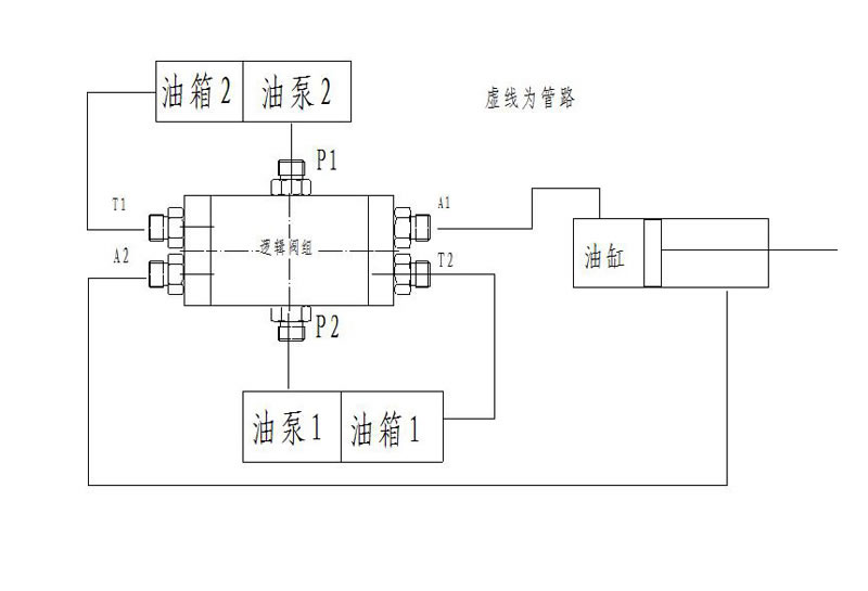
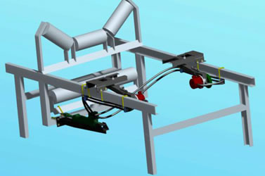
3. Working Principle
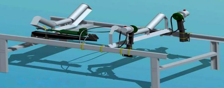
The device is composed of a power output device composed of a detection wheel and an oil pump, a logic valve, and an actuator composed of an oil cylinder, which is then connected to the deviation correction roller frame
When the belt is running in the center, it does not come into contact with the left and right detection wheels, indicating normal operation. If the belt is running on the left side, activate the left power output device, and the actuator adjusts the position of the correction roller based on the logic valve judgment, generating reverse thrust and pushing the belt towards the middle side. On the contrary, when the belt is tilted to the right, the right power output device is activated, and the actuator adjusts the position of the correction roller based on the logic valve judgment, generating reverse thrust and pushing the belt towards the middle side
4.Selection instructions
1. The device can be installed in places where belt deviation correction is required. Please refer to the user manual before installation< Br/> 2. The hydraulic oil used in the high-efficiency hydraulic centering device is 32 or 46 anti wear, with a refueling and filtering accuracy of 20< Br/> 3. For new users, our company will send technical personnel to guide installation and debugging
4. Deviation correction installation process
Preparation before installation: According to the running direction of the belt conveyor and the installation position of the centering roller, the method shown in Figure 1 can be selected for the installation position of the correction device:
Upper deviation correction installation:
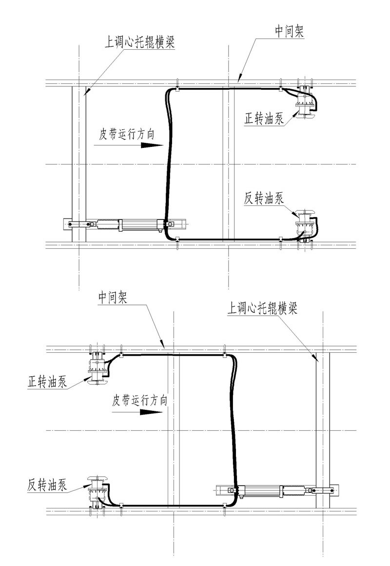
!!! Installation errors can cause the correction machine to have the opposite effect and may also damage the oil pump. Attention should be paid during installation.
Lower correction installation:
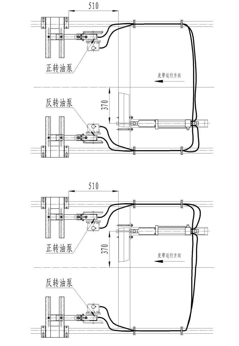
!!! Installation errors can cause the correction machine to have the opposite effect and may also damage the oil pump. Attention should be paid during installation.
5. Installation of oil cylinder
Select the appropriate position of the centering roller to maximize the efficiency of the correction machine. The centering roller must be at least 5m away from various directional rollers; And the centering roller should also be about 10mm higher than the adjacent fixed roller
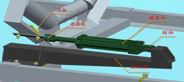
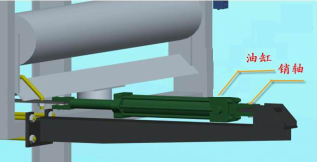
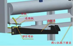
The oil cylinder is fixed to the lower crossbeam of the centering roller through the oil cylinder seat, and the lower crossbeam is generally made of channel steel. The installation process can be divided into the following steps:
① Install the piston rod clamp as shown in the figure on the lower center roller crossbeam, do not tighten the nut first, and then tighten the nut when the oil cylinder is adjusted to the appropriate position during installation
② Place the oil cylinder seat on the lower crossbeam of the centering roller, do not tighten the nut first, and then tighten the nut when the oil cylinder is installed and adjusted to the appropriate position. Do not tighten the nut either
③ Install the two ear ring holes of the hydraulic cylinder onto the piston rod clamp and cylinder seat with pins according to the positions shown in the figure
Then tighten the air filter cap
6. Connection of oil pipes:
Due to the fact that the oil cylinder is placed on one side, the oil pipes are divided into long side pipes and short side pipes. Two short side pipes are used on one side near the oil cylinder, and two long side pipes are used on the other side. Both ends of the oil pipe are flexible joints; The flexible joint is divided into direct joint and bent joint. When installing the oil pipe, in order to ensure smooth installation and long service life of the oil pipe, the two joints at the lower part of the valve and the two joints at the oil outlet of the oil pump use bent joints as shown in Figure 5, while the two joints at the upper part of the valve (outlet at both ends of the tee) and the two joints at the oil return port of the oil tank use direct joints. As shown in Figure 6, based on performance, our valves have three way and four way valves. The oil pipe connection method for the four way valve is shown in Figure 7.
When installing oil pipes, pay attention to the following two points:
(1) All joints use O-ring seals. The O-ring is simple and reliable, but it is important to ensure that the O-ring is in the groove during installation. The installation of the O-ring on the vertical surface is easy to fall off. The use of Vaseline ointment or butter can make the installation easier. The installation method is shown in the following figure.
(2) Do not remove the pipe sleeve and joint sleeve of all oil ports before connecting them. It is difficult to thoroughly clean the joints after being contaminated by dust and dirt on site, which will ultimately affect the working status of the hydraulic system.
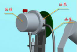
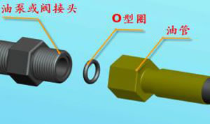
Pump component oil pipe connection Installation of joints
Oil pipe exhaust:The purpose of exhaust is to exhaust the air in the oil circuit during installation, so that there is no air present inside the valve block and cylinder. When venting, tighten the oil pump and the oil pipe joint. Lift the outlet of the other end of the oil pipe slightly higher, turn the inspection wheel of the oil pump, and observe the exhaust situation at the oil pipe outlet. If there is basically no air in the continuously discharged oil, immediately connect the oil pipe to the valve joint. The return line from the oil cylinder to the fuel tank does not require venting.
Fixation of oil pipes:Each deviation correction machine is equipped with 6 oil pipe clamps, which can fix the oil pipes on the inner side of the intermediate frame. The installation method is shown in the following figure. When fixing the oil pipe, it should be noted that there should be expansion and contraction allowance for the oil pipe at the oil cylinder and oil pump
7. Installation of inspection wheel:
The starting point of the inspection drive wheel is the position where the inspection drive wheel contacts the belt, which is actually the position where the correction machine starts working after the belt deviates. The design of WY hydraulic deviation correction machine allows users to easily adjust and set the starting point of the deviation correction machine
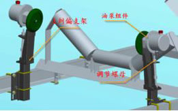
The adjustment of the starting point of work can be divided into left right adjustment and high low adjustment. The left and right position adjustment is achieved by adjusting the nuts at both ends of the screw rod. The upper nut determines the left and right positions of the inspection drive wheel, while the lower nut determines the maximum lateral thrust borne by the inspection drive wheel through the spring. On the premise of ensuring the normal operation of the inspection wheel, the smaller the force, the better. The height position of the starting point of the upper correction machine is achieved by adjusting the height of the square tube. After adjusting the height, tighten the U-bolt 2
Due to the contraction of the belt caused by the rotation of the centering roller, it will have an impact on the starting point of the inspection drive wheel. In order to reduce this impact, the installation position of the inspection drive wheel and pump components must be at least 150mm away from the centering roller, and can be placed before and after the centering roller. Do not tighten the nuts of the bolts until the position of the deviation correction bracket seat and the deviation correction bracket is adjusted properly, so that the bracket seat can slide freely, and the deviation correction bracket can slide up and down easily. Tighten the nuts after the position is determined
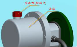
8. Refueling: After all components are installed, start refueling the system. When refueling, unscrew the air filter cap. The position of the air filter cap is as shown in the figure. Observe the oil level through the oil level gauge and refuel to 4/5 of the oil tank;
Installation of oil cylinder seat Installation of oil pump
9. Adjust the starting point of the inspection wheel action
The starting point of the inspection drive wheel is the position where the inspection drive wheel contacts the belt, which is actually the position where the correction machine starts working after the belt deviates. The design of WY hydraulic deviation correction machine allows users to easily adjust and set the starting point of the deviation correction machine. The adjustment of the starting point of work can be divided into left right adjustment and high low adjustment.
The left and right positions of the starting point of the lower correction machine are achieved by adjusting the position of the bracket seat. The bracket seat can move left and right on the fixed roller crossbeam, which is usually made of angle steel (refer to Figure 2). After moving to the appropriate position, tighten the angle steel clip nut. The height position of the starting point of the lower correction machine is determined by the screw nut on the bracket (refer to Figure 2). The upper nut determines the height position of the inspection drive wheel, while the lower nut determines the maximum positive pressure borne by the inspection drive wheel through a spring. On the premise of ensuring the normal operation of the inspection wheel, the smaller the force, the better. The tighter the spring is tightened, the greater the positive pressure on the inspection drive wheel.
10. Check Closing
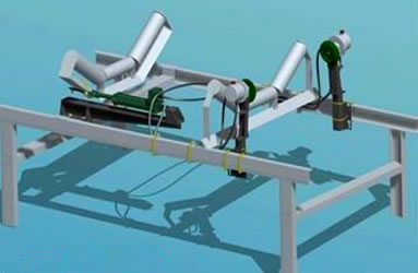
After all installations are completed, simulate belt deviation, rotate the left and right inspection wheels in turn, and let the oil cylinder drive the centering roller to rotate, cycling 5 times.
Check the sealing condition of all joints during the cycle; Check all bolted connections;
Check that the oil pipe and belt do not interfere.
The installation effect is shown in the figure.
Prev:WY belt hydraulic corrector
Next:None

EACCOR mobile station

EACCOR wechat public account